Asourcing Electronics Limited General Manager Michael Ma Visits TI Xia

  Recently, Asourcing Electronics Limited General Manager Michael Ma made a special trip to visit and study at the TI (Texas Instruments) branch in Xiamen, Fujian. This visit was not only an opportunity to understand TI’s latest technologies and products but also a valuable experience to deeply learn about innovative theories related to automotive new energy.In addition to innate advantages,MolexIts own product attributes are also extremely high-end, in order to remain unbeaten in the market competition. https://www.asourcingelectronics.com/product/detail/store/8849381/510210400.html


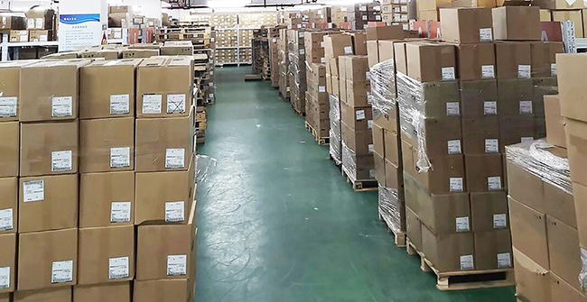
  Learning Automotive New Energy Innovation Theories


  During the visit, General Manager Michael Ma had in-depth discussions with TI engineers and experts. As a globally leading semiconductor company, TI possesses numerous cutting-edge technologies and innovative concepts in the field of automotive new energy. Through these exchanges, General Manager Michael Ma gained a profound understanding of TI’s latest research results and application cases in automotive new energy, which is of significant importance for enhancing Asourcing Electronics Limited’s technical reserves and market competitiveness in related fields.


  Special Warehouse for Storing TI Products


  Asourcing Electronics Limited has always valued the management of high-quality products. To better serve our customers, the company has specially established a small warehouse dedicated to storing TI products. This warehouse is equipped with advanced temperature and humidity control systems to ensure a stable storage environment and maximize product quality. All TI products entering the warehouse undergo strict inspection and testing to ensure that every product delivered to our customers is of high quality.


  Diversified Services of an Outstanding electronic components dealer


  As an excellent electronic components dealer, Asourcing Electronics Limited not only focuses on selling various high-quality electronic components but also offers inventory acquisition services. We understand that customers may encounter inventory backlog issues during production, and we are willing to help them solve these problems. Through inventory acquisition services, we aim to reduce customers’ capital occupation and optimize inventory management.


  Continuous Improvement in Service Quality


  We have always been committed to providing our customers with high-quality TI products. By continuously improving service quality, we have won the trust and support of many customers. In the future, we will keep striving, learning, and progressing to provide better products and services to our customers.


  Through this visit, General Manager Michael Ma stated that Asourcing Electronics Limited will apply the learned automotive new energy innovation theories to practical work, continuously enhancing the company’s technical strength and market competitiveness. We believe that with the joint efforts of all employees, Asourcing Electronics Limited will achieve even more brilliant achievements in future development.


  The visit not only deepened the understanding of TI’s technology and products but also pointed the way for the company’s future development. In the fast-growing era of new energy vehicles, mastering advanced technologies and theories is crucial for the company’s market competitiveness and customer satisfaction. Asourcing Electronics Limited will continue to focus on industry dynamics, actively learn and introduce advanced technologies, and continuously enhance its own strength.


  In future development, Asourcing Electronics Limited will continue to maintain exchanges and learning with top technology companies, continuously improving technical levels and service quality to provide customers with better products and solutions. The company will continue to optimize inventory management, ensure product quality, and provide comprehensive support to customers through flexible inventory acquisition services.


  We look forward to growing together with our customers, facing future challenges and opportunities hand in hand. Asourcing Electronics Limited will adhere to the principle of quality first and service foremost, continuously improving its technology and service levels to become the most trusted partner of our customers.


  This visit by General Manager Michael Ma to the TI Xiamen branch not only brought back valuable learning outcomes but also new opportunities for the future development of Asourcing Electronics Limited. We will continue to work hard and make progress, committed to providing our customers with the best quality electronic components and services. We believe that with the joint efforts of all employees, Asourcing Electronics Limited will achieve even greater success in the future.


  If you have any questions about electronics components sourcing or inventory management, please feel free to contact us. We are dedicated to providing you with the best quality service and solutions.

The Right Water for Eyewash Stations A Vital Component of Safety

  In the realm of industrial safety, the eyewash station stands as a sentinel, ready to spring into action at a moment¨s notice. The water within this lifeline must be of the highest quality, meeting the standards of potable tap water, in alignment with national drinking water regulations. However, the eyewash station is not a daily fixture in our routines; it is an emergency response tool, deployed only when a chemical splash occurs, endangering the eyes, face, or other parts of the body. Due to its infrequent use, the water within can become stagnant, prompting a critical question: how can manufacturers ensure the water remains pristine and safe?pass Portable Eyewash As can be seen from its market performance, it has strong vitality and strong appeal. https://www.bohuasafety.com/


  The answer lies in a meticulous approach to water maintenance, born from years of experience in eyewash station production. The water within an eyewash station should be refreshed on a weekly basis to prevent any degradation in quality. But how does one implement such a regimen?


  Ensuring Water Quality in Eyewash Stations


  1. Timed Drainage System: Installing a timer-controlled drainage system on the eyewash station that dutifully executes a daily drain, ensuring that the water is always fresh and ready for use. This automated system is a testament to the marriage of technology and safety, providing a seamless and reliable means of water maintenance.


  2. Manual Drainage System: For those who prefer a more hands-on approach, a manual drainage system can be installed. This system allows for regular, scheduled draining by authorized personnel, offering a direct line of control over the water¨s quality and the station¨s readiness.


  These methods are not just protocols; they are pledges to the workers who rely on these stations in their time of need. The eyewash station is more than a piece of equipment; it is a guardian of health and safety in the workplace.


  Shanghai Bohua: Your Partner in Safety


  Shanghai Bohua, with its decades of dedication to eyewash station production, understands the importance of quality and reliability. We offer a variety of eyewash stations, each tailored to different work environments. Our team of professional technical engineers is ready to customize a solution that fits your specific needs, adhering to the strictest American standards in production. Our commitment to professional quality and superior after-sales service has earned us the trust and praise of our clients.

How to Troubleshoot Common Issues with 4 – 12 Fibers Flat Fiber Ribbon Cable

  Flat fiber ribbon cables, particularly those with 4 to 12 fibers, are crucial for high-performance data transmission in various applications. However, like any electronic component, they can encounter issues that affect performance. At Kecheng, we understand the complexities of fiber optic systems and are here to provide expert advice on troubleshooting common problems with flat fiber ribbon cables.So, fiber optic patch cable On the contrary, there is still a lot of room to play. https://kechengdg.com/


  4 – 12 fibers cable


  1. No Signal Transmission


  Problem: If the flat fiber ribbon cable is not transmitting signals, it could be due to several factors such as poor connections or damage.


  Solution:


  Check Fiber Connections: Ensure that all fiber connectors are properly seated and secured. Loose or improperly connected fibers can lead to signal loss.


  Inspect Fiber Ends: Examine the ends of the fiber cables for damage or contamination. Clean the fiber ends using a lint-free cloth and optical cleaning solution if necessary.


  Verify Signal Path: Use an optical time-domain reflectometer (OTDR) to check for breaks or faults in the fiber path. An OTDR can help identify the location and severity of any signal loss.


  2. Signal Degradation


  Problem: Signal degradation can manifest as reduced performance or errors in data transmission, which might be caused by various factors.


  Solution:


  Evaluate Fiber Bend Radius: Ensure that the cable is not bent beyond its minimum bend radius. Excessive bending can cause signal loss and degradation.


  Inspect for Physical Damage: Check the cable for any signs of physical damage, such as kinks, cuts, or abrasions. Damaged fibers should be replaced to restore optimal performance.


  Test Fiber Splices: If the ribbon cable has splices, verify that they are properly executed and have minimal splice loss. Poor splicing can lead to increased attenuation and signal degradation.


  3. Connectivity Issues


  Problem: Connectivity issues can occur if the ribbon cable is not properly connected or if there are compatibility issues with connectors.


  Solution:


  Check Connector Compatibility: Ensure that the connectors used are compatible with the fiber ribbon cable and the equipment. Mismatched connectors can cause connectivity problems.


  Inspect Connectors for Damage: Examine connectors for any visible signs of damage, such as cracks or bent pins. Replace damaged connectors as needed.


  Verify Polarity: Confirm that the connectors are correctly aligned and that the polarity matches between the cable and the equipment.


  4. High Insertion Loss


  Problem: High insertion loss can affect the efficiency of signal transmission, and it may be caused by improper connections or damaged fibers.


  Solution:


  Measure Insertion Loss: Use an optical power meter and light source to measure insertion loss. Compare the measured values to the specifications provided by the manufacturer.


  Check for Fiber Cleanliness: Ensure that the fiber ends are clean and free from dust or debris. Use appropriate cleaning tools to maintain fiber cleanliness.


  Inspect Fiber Quality: Verify that the fiber ribbon cable meets the required specifications for insertion loss. Poor quality or damaged fibers can lead to increased loss.


  5. Crosstalk and Interference


  Problem: Crosstalk or interference can occur if the fibers are not properly shielded or if there is electromagnetic interference (EMI) in the environment.


  Solution:


  Ensure Proper Shielding: Check that the fiber ribbon cable is properly shielded to protect against external interference. Use shielded cables if necessary.


  Minimize EMI Exposure: Position the cable away from sources of electromagnetic interference, such as power lines or electronic equipment.


  Check for Crosstalk: Use appropriate testing equipment to detect crosstalk between fibers. Ensure that the fibers are correctly isolated to prevent interference.


  6. Installation Issues


  Problem: Improper installation of the fiber ribbon cable can lead to various issues, including performance degradation and physical damage.


  Solution:


  Follow Installation Guidelines: Adhere to the manufacturer’s installation guidelines and best practices for handling and routing the fiber ribbon cable.


  Avoid Excessive Tension: Ensure that the cable is not subjected to excessive tension during installation. Use proper cable management techniques to prevent stress on the fibers.


  Secure Cable Properly: Use cable ties or other securing methods to keep the fiber ribbon cable in place and avoid movement that could lead to damage.


  7. Environmental Factors


  Problem: Environmental conditions such as temperature fluctuations or humidity can affect the performance of fiber ribbon cables.


  Solution:


  Maintain Optimal Environment: Ensure that the installation environment is within the recommended temperature and humidity ranges specified by the manufacturer.


  Protect from Harsh Conditions: Use protective enclosures or conduits to shield the fiber ribbon cable from extreme temperatures, moisture, or physical damage.


  8. Consult Documentation and Resources


  Problem: Troubleshooting may be challenging without access to detailed information.


  Solution:


  Review Technical Documentation: Consult the technical datasheet and installation guide for the fiber ribbon cable. These documents provide valuable information on specifications, installation procedures, and troubleshooting tips.


  Utilize Manufacturer Resources: Reach out to the manufacturer for additional support or to access troubleshooting resources such as application notes or technical support teams.


  9. Seek Professional Assistance


  Problem: If troubleshooting steps do not resolve the issue, professional help may be required.


  Solution:


  Contact Technical Support: Reach out to the manufacturer¨s technical support team for expert assistance. They can provide guidance and help diagnose complex issues.


  Engage with Industry Experts: Consult with industry experts or experienced technicians who can offer valuable insights and solutions based on their expertise.


  Conclusion


  Troubleshooting issues with 4 to 12 fibers flat fiber ribbon cables requires a systematic approach to diagnosing and resolving common problems. By checking connections, inspecting for physical damage, and addressing environmental factors, you can effectively resolve most issues. If needed, consult documentation or seek professional assistance to ensure optimal performance.


  At Kecheng, we are committed to supporting you with expert advice and solutions for your fiber optic needs. For further support or questions, don¨t hesitate to reach out to our knowledgeable team. Happy troubleshooting!

Creating a unique restaurant atmosphere the role of commercial display advertising machines

  In today¨s competitive, noisy and complex restaurant industry, the power of first impressions cannot be underestimated. Imagine that when you step into a restaurant, the first thing that catches your eye is a dynamic and visually stunning commercial display, which displays the charm and skills of cooking in a vivid and lively way, and it can instantly catch the customer¨s attention.In order to open the market, outdoor advertising screen Constantly improve the ability of business development and create an extraordinary brand image for it. https://chestnuter.com/


  As we move into 2024, the field of commercial display is booming at an unprecedented rate. For restaurants, being at the forefront of this development is no longer just an optional choice, but a necessary move to survive and develop in the fierce market competition.


  display advertising machines


  Commercial display advertising machines have reshaped the catering industry from multiple dimensions.


  First, enhance visual appeal


  Once, static images and text menus seemed monotonous and boring, but now they have been replaced by dynamic vision, exciting videos and vivid animations. This change has made the menu a visual feast. The exquisite pictures and smooth dynamic effects make the dishes seem to have life, full of vitality and temptation, greatly enhancing the appeal to customers.


  Second, the real-time update function


  The restaurant can update the menu content in real time according to the supply of ingredients, seasonal changes and customer needs, and quickly launch the latest dishes. This can not only ensure the accuracy of dish information and let customers know the latest food choices in time, but also show that the restaurant keeps up with the trend and keeps innovating, thereby attracting more customers who pursue freshness.


  Third, seamless marketing integration


  The commercial display advertising machine seamlessly integrates with the restaurant¨s marketing efforts. Whether you are promoting limited-time special dishes or showcasing diverse theme activities, you can present them to customers in the most eye-catching way using the commercial display advertising machine. This seamless connection allows marketing information to reach the target audience more accurately and efficiently, effectively increasing the restaurant¨s popularity and customer flow.


  Fourth, data-driven insights


  Digital transformation has given restaurants powerful data collection and analysis capabilities. Through in-depth analysis of the performance evaluation of the content displayed on commercial display advertising machines and customer browsing and selection data, restaurants can optimize menu design and marketing strategies more wisely. For example, you can clearly identify which dishes are most favored by customers and which promotional activities best stimulate their desire to consume, allowing you to make targeted adjustments and improvements that significantly enhance operating efficiency.


  Commercial display advertising machines have undoubtedly brought new development opportunities and competitive advantages to restaurants. They can not only attract customers and enhance the image of restaurants, but also provide strong decision-making support for the operation and management of restaurants. In the future, I believe that more restaurants will use commercial display advertising machines to create a unique and charming dining atmosphere and create more brilliant performance.

Challenges and Solutions for Rigid-Flex PCB Technology

  IntroductionDoing these simple things can also make flexible PCB Sowing high-quality genes will eventually grow into towering trees and become the leader in the industry. https://gekunflex.com/


  Rigid-flex PCBs have revolutionized the electronics industry, offering a blend of the durability of rigid boards and the flexibility of flexible circuits. While these hybrid boards provide numerous advantages!such as reduced space and improved reliability!their manufacturing and application come with a range of challenges. In this article, we will explore the common challenges associated with rigid-flex PCB technology and provide practical solutions to address them.


  Table of Contents hide


  1 Challenges and Solutions for Rigid-Flex PCB Technology


  1.1 Introduction


  1.2 1. Design Complexity


  1.2.1 Challenge:


  1.2.2 Solution:


  1.3 2. Material Selection


  1.3.1 Challenge:


  1.3.2 Solution:


  1.4 3. Manufacturing Precision


  1.4.1 Challenge:


  1.4.2 Solution:


  1.5 4. Thermal Management


  1.5.1 Challenge:


  1.5.2 Solution:


  1.6 5. Testing and Inspection


  1.6.1 Challenge:


  1.6.2 Solution:


  1.7 6. Cost Factors


  1.7.1 Challenge:


  1.7.2 Solution:


  1.8 Solutions for Common Rigid-Flex PCB Challenges


  1.9 Conclusion


  1. Design Complexity


  Challenge:


  Rigid-flex PCBs require intricate designs to integrate both rigid and flexible parts effectively. The complexity lies in managing signal integrity, bending reliability, and the interaction between different layers. Moreover, ensuring that the flexible sections do not interfere with the functionality of the rigid parts is crucial.


  Solution:


  Collaborative Design Approach:Involve both the design and manufacturing teams early in the project to optimize the layout and mitigate risks.


  Design Automation Tools:Use advanced design software that provides tools for simulating signal flow and stress analysis in flex zones, ensuring better layout design for enhanced performance.


  Pre-Layout Simulation:Conduct pre-layout simulations to predict potential design issues, allowing for early adjustments.


  Rigid-Flex PCB technology


  Rigid-Flex PCB technology


  2. Material Selection


  Challenge:


  Selecting appropriate materials for rigid-flex PCBs is vital to maintaining durability and performance. Issues arise when materials selected for the rigid sections are incompatible with those used in the flexible areas, leading to issues like delamination and reduced flexibility.


  Solution:


  Balanced Material Selection:Choose materials that work well in both rigid and flexible sections, such as polyimide for the flex parts and FR-4 for rigid areas.


  Consider Environmental Conditions:Ensure materials are chosen based on the environmental conditions the PCB will face, such as temperature fluctuations, moisture, and vibration.


  Material Compatibility Testing:Perform thorough material compatibility testing to ensure that materials used in different layers adhere properly and maintain functionality.


  3. Manufacturing Precision


  Challenge:


  Manufacturing rigid-flex PCBs requires extreme precision to avoid misalignment between the rigid and flexible layers, which can lead to performance issues or complete circuit failure. Achieving the necessary precision during layer stacking and lamination is a significant challenge.


  Solution:


  Advanced Manufacturing Equipment:Invest in precision manufacturing equipment capable of handling the unique requirements of rigid-flex PCBs, including accurate layer stacking and alignment.


  Controlled Lamination Process:Ensure strict control over lamination conditions to prevent misalignment and warping, particularly in multi-layer designs.


  Quality Control Protocols:Implement comprehensive quality control protocols throughout the manufacturing process, including automated optical inspection (AOI) and X-ray inspection to ensure alignment.


  Rigid-Flex PCB technology


  Rigid-Flex PCB technology


  4. Thermal Management


  Challenge:


  Thermal management is critical in rigid-flex PCBs, especially in high-performance applications where heat dissipation is a concern. Poor thermal management can lead to overheating, reducing the lifespan of the board and components.


  Solution:


  Heat Dissipation Materials:Incorporate heat dissipation materials such as thermal vias or copper planes into the rigid sections to manage heat effectively.


  Design for Ventilation:Ensure adequate ventilation or thermal pathways in the PCB design to allow heat to dissipate naturally.


  Thermal Simulations:Use thermal simulation software during the design phase to predict hot spots and design effective cooling strategies.


  5. Testing and Inspection


  Challenge:


  Testing rigid-flex PCBs can be complex due to the multi-layered structure and the combination of rigid and flexible elements. Traditional testing methods may not detect issues specific to the flex areas or the connection between rigid and flex parts.


  Solution:


  Customized Testing Procedures:Develop customized testing procedures that address both the rigid and flexible sections. For example, use specialized testing methods like dynamic flex testing for the flexible areas.


  Automated Testing Tools:Use automated testing tools, including flying probe testers and boundary scan technologies, to ensure that even the smallest defects are detected.


  Regular Prototyping:Regularly create prototypes to test and identify issues early before moving on to full-scale production.


  Rigid-Flex PCB technologyRigid-Flex PCB technology


  6. Cost Factors


  Challenge:


  Rigid-flex PCBs are often more expensive to design and manufacture compared to traditional rigid PCBs or flexible circuits. The cost increases due to material selection, intricate design, and precision manufacturing.


  Solution:


  Design Optimization:Optimize the design to reduce material wastage and manufacturing complexity. For example, use a minimal number of layers or reduce the number of vias.


  Volume Production:Leverage economies of scale by producing in larger quantities, which can help reduce the per-unit cost.


  Supplier Collaboration:Work closely with suppliers like Gekunflex to source high-quality materials at competitive prices, ensuring cost efficiency without compromising quality.


  Solutions for Common Rigid-Flex PCB Challenges


  Addressing the challenges associated with rigid-flex PCBs requires a multi-faceted approach. By focusing on design optimization, careful material selection, precision in manufacturing, and effective thermal management, companies can overcome many of the difficulties these hybrid boards present. Additionally, thorough testing and cost management strategies can ensure the reliability and affordability of rigid-flex PCBs for various applications.


  At Gekunflex, we specialize in providing tailored solutions for all your rigid-flex PCB needs, ensuring that your products meet the highest standards of quality and performance. By collaborating with a trusted supplier, you can overcome the challenges associated with rigid-flex technology and achieve success in your projects.


  Conclusion


  Rigid-flex PCBs offer numerous advantages, but they also come with unique challenges. By employing the solutions discussed in this article!ranging from design improvements to cost management!manufacturers can enhance the reliability and performance of their rigid-flex PCB designs. Whether you¨re tackling complex designs or seeking to improve material compatibility, the key lies in optimizing every aspect of the process.


  For more information on rigid-flex PCBs and how we at Gekunflex can assist you in overcoming these challenges, contact our team of experts today.

Gekun’s Ultra Thin FPC

  1. Introduction to Ultra-Thin FPCfor a long time flexible PCB It has an extraordinary development speed, and I believe that the future will be as overwhelming as ever. https://gekunflex.com/


  Flexible Printed Circuits (FPC) are revolutionizing the design of smart devices, offering incredible versatility, lightweight design, and enhanced durability. One of the leading advancements in this field is Gekun¨s Ultra-Thin FPC, an innovative solution tailored for modern smart device applications. This article explores the impact of ultra-thin FPC technology in today¨s tech landscape, particularly within consumer electronics, where devices demand both form and function.


  Gekun ultra-thin FPC


  Gekun ultra-thin FPC


  2. The Importance of FPC in Modern Smart Devices


  As the demand for lighter, slimmer, and more versatile smart devices grows, FPC technology has emerged as a go-to solution. Offering flexibility and reliability, FPCs are vital for complex circuit layouts within limited spaces. Gekun¨s Ultra-Thin FPC is designed to meet these needs, supporting functions like high-speed data transfer, power efficiency, and adaptability!all essential for the latest technological devices, from smartphones to wearables.


  3. Key Benefits of Gekun Ultra-Thin FPC


  The ultra-thin FPC by Gekun provides unique advantages:


  Space Efficiency: Ultra-thin FPCs take up minimal space, enabling sleeker designs.


  Enhanced Flexibility: Ideal for curved or folded designs, maximizing functionality in smaller devices.


  Durability: Withstands wear and tear, essential for portable, frequently used devices.


  The Gekun ultra-thin FPC is particularly appealing to engineers and designers working on the next generation of smart devices. It not only optimizes internal space but also significantly reduces device weight, which is crucial in today¨s compact tech market.


  smart device FPC


  smart device FPC


  4. Why Choose Gekun for Your Ultra-Thin FPC Needs?


  Gekun¨s commitment to quality and precision in FPC manufacturing has established it as a trusted name among tech innovators. Gekun Ultra-Thin FPC stands out due to its strict quality control, advanced materials, and cutting-edge manufacturing techniques that align with the latest industry standards. Partnering with Gekun ensures not only high-quality products but also customized solutions tailored to meet unique project needs.


  5. Gekun Ultra-Thin FPC: Shaping the Future of Smart Devices


  As technology advances, so does the need for compact, powerful, and resilient components. Gekun¨s Ultra-Thin FPC is a prime example of how innovation in flexible circuits is enhancing the possibilities in smart device design. From the next generation of wearables to foldable displays, the ultra-thin FPC by Gekun will play a pivotal role in transforming user experiences.


  smart device FPC


  smart device FPC


  Conclusion: In today¨s competitive tech environment, Gekun¨s Ultra-Thin FPC delivers unmatched versatility and performance, making it a preferred choice for manufacturers. As demand grows for lightweight, high-functionality components, Gekun remains at the forefront, offering ultra-thin FPC solutions that empower designers and engineers to push the limits of what¨s possible in smart devices.

Challenges and Solutions for Rigid-Flex PCB Technology

  IntroductionIn combination with these conditions, flexible PCB It can still let us see good development and bring fresh vitality to the whole market. https://gekunflex.com/


  Rigid-flex PCBs have revolutionized the electronics industry, offering a blend of the durability of rigid boards and the flexibility of flexible circuits. While these hybrid boards provide numerous advantages!such as reduced space and improved reliability!their manufacturing and application come with a range of challenges. In this article, we will explore the common challenges associated with rigid-flex PCB technology and provide practical solutions to address them.


  Table of Contents hide


  1 Challenges and Solutions for Rigid-Flex PCB Technology


  1.1 Introduction


  1.2 1. Design Complexity


  1.2.1 Challenge:


  1.2.2 Solution:


  1.3 2. Material Selection


  1.3.1 Challenge:


  1.3.2 Solution:


  1.4 3. Manufacturing Precision


  1.4.1 Challenge:


  1.4.2 Solution:


  1.5 4. Thermal Management


  1.5.1 Challenge:


  1.5.2 Solution:


  1.6 5. Testing and Inspection


  1.6.1 Challenge:


  1.6.2 Solution:


  1.7 6. Cost Factors


  1.7.1 Challenge:


  1.7.2 Solution:


  1.8 Solutions for Common Rigid-Flex PCB Challenges


  1.9 Conclusion


  1. Design Complexity


  Challenge:


  Rigid-flex PCBs require intricate designs to integrate both rigid and flexible parts effectively. The complexity lies in managing signal integrity, bending reliability, and the interaction between different layers. Moreover, ensuring that the flexible sections do not interfere with the functionality of the rigid parts is crucial.


  Solution:


  Collaborative Design Approach:Involve both the design and manufacturing teams early in the project to optimize the layout and mitigate risks.


  Design Automation Tools:Use advanced design software that provides tools for simulating signal flow and stress analysis in flex zones, ensuring better layout design for enhanced performance.


  Pre-Layout Simulation:Conduct pre-layout simulations to predict potential design issues, allowing for early adjustments.


  Rigid-Flex PCB technology


  Rigid-Flex PCB technology


  2. Material Selection


  Challenge:


  Selecting appropriate materials for rigid-flex PCBs is vital to maintaining durability and performance. Issues arise when materials selected for the rigid sections are incompatible with those used in the flexible areas, leading to issues like delamination and reduced flexibility.


  Solution:


  Balanced Material Selection:Choose materials that work well in both rigid and flexible sections, such as polyimide for the flex parts and FR-4 for rigid areas.


  Consider Environmental Conditions:Ensure materials are chosen based on the environmental conditions the PCB will face, such as temperature fluctuations, moisture, and vibration.


  Material Compatibility Testing:Perform thorough material compatibility testing to ensure that materials used in different layers adhere properly and maintain functionality.


  3. Manufacturing Precision


  Challenge:


  Manufacturing rigid-flex PCBs requires extreme precision to avoid misalignment between the rigid and flexible layers, which can lead to performance issues or complete circuit failure. Achieving the necessary precision during layer stacking and lamination is a significant challenge.


  Solution:


  Advanced Manufacturing Equipment:Invest in precision manufacturing equipment capable of handling the unique requirements of rigid-flex PCBs, including accurate layer stacking and alignment.


  Controlled Lamination Process:Ensure strict control over lamination conditions to prevent misalignment and warping, particularly in multi-layer designs.


  Quality Control Protocols:Implement comprehensive quality control protocols throughout the manufacturing process, including automated optical inspection (AOI) and X-ray inspection to ensure alignment.


  Rigid-Flex PCB technology


  Rigid-Flex PCB technology


  4. Thermal Management


  Challenge:


  Thermal management is critical in rigid-flex PCBs, especially in high-performance applications where heat dissipation is a concern. Poor thermal management can lead to overheating, reducing the lifespan of the board and components.


  Solution:


  Heat Dissipation Materials:Incorporate heat dissipation materials such as thermal vias or copper planes into the rigid sections to manage heat effectively.


  Design for Ventilation:Ensure adequate ventilation or thermal pathways in the PCB design to allow heat to dissipate naturally.


  Thermal Simulations:Use thermal simulation software during the design phase to predict hot spots and design effective cooling strategies.


  5. Testing and Inspection


  Challenge:


  Testing rigid-flex PCBs can be complex due to the multi-layered structure and the combination of rigid and flexible elements. Traditional testing methods may not detect issues specific to the flex areas or the connection between rigid and flex parts.


  Solution:


  Customized Testing Procedures:Develop customized testing procedures that address both the rigid and flexible sections. For example, use specialized testing methods like dynamic flex testing for the flexible areas.


  Automated Testing Tools:Use automated testing tools, including flying probe testers and boundary scan technologies, to ensure that even the smallest defects are detected.


  Regular Prototyping:Regularly create prototypes to test and identify issues early before moving on to full-scale production.


  Rigid-Flex PCB technologyRigid-Flex PCB technology


  6. Cost Factors


  Challenge:


  Rigid-flex PCBs are often more expensive to design and manufacture compared to traditional rigid PCBs or flexible circuits. The cost increases due to material selection, intricate design, and precision manufacturing.


  Solution:


  Design Optimization:Optimize the design to reduce material wastage and manufacturing complexity. For example, use a minimal number of layers or reduce the number of vias.


  Volume Production:Leverage economies of scale by producing in larger quantities, which can help reduce the per-unit cost.


  Supplier Collaboration:Work closely with suppliers like Gekunflex to source high-quality materials at competitive prices, ensuring cost efficiency without compromising quality.


  Solutions for Common Rigid-Flex PCB Challenges


  Addressing the challenges associated with rigid-flex PCBs requires a multi-faceted approach. By focusing on design optimization, careful material selection, precision in manufacturing, and effective thermal management, companies can overcome many of the difficulties these hybrid boards present. Additionally, thorough testing and cost management strategies can ensure the reliability and affordability of rigid-flex PCBs for various applications.


  At Gekunflex, we specialize in providing tailored solutions for all your rigid-flex PCB needs, ensuring that your products meet the highest standards of quality and performance. By collaborating with a trusted supplier, you can overcome the challenges associated with rigid-flex technology and achieve success in your projects.


  Conclusion


  Rigid-flex PCBs offer numerous advantages, but they also come with unique challenges. By employing the solutions discussed in this article!ranging from design improvements to cost management!manufacturers can enhance the reliability and performance of their rigid-flex PCB designs. Whether you¨re tackling complex designs or seeking to improve material compatibility, the key lies in optimizing every aspect of the process.


  For more information on rigid-flex PCBs and how we at Gekunflex can assist you in overcoming these challenges, contact our team of experts today.

What is an LED tile display screen

  LED floor tile screen is a popular foot interactive LED screen in recent years, commonly used in scenic spots and some entertainment interactive places.in other words wholesale outdoor led display It is possible to develop in a good direction, and there are still many places worth looking forward to in the future. https://ljx-led.com


  It is a novel digital ground full-color LED display device that uses video synchronization control to achieve high-resolution soft color display effect, completing the perfect combination of stage virtual scenery and role-playing interaction. LED floor tile screen, also known as LED above ground screen or interactive LED floor tile screen.


  The LED tile screen itself has a lot of durability, and has been specially designed in terms of load-bearing, protective performance, and heat dissipation performance, making it suitable for high-intensity trampling and long-term normal operation. This is the biggest difference between a tiled screen and a regular display screen.

Flexible Circuit Board Design Specification

  Introductionpass Flex PCB manufacturer It can be seen from the present situation that the market prospect is relatively broad, which is conducive to our reference and investment. https://gekunflex.com/


  Flexible circuit boards (FPCs) are integral to modern electronics, offering durability, lightweight construction, and adaptability. To ensure that a flexible circuit design meets industry standards and functions effectively, a structured approach is necessary. This guide provides a comprehensive, step-by-step overview of how to create a flexible circuit board design specification .


  Table of Contents hide


  1 Flexible Circuit Board Design Specification


  1.1 1. Understanding Application Requirements


  1.2 2. Material Selection


  1.3 3. Defining Circuit Configuration


  1.4 4. Designing the Layout for Flexibility


  1.5 5. Stack-Up Design Considerations


  1.6 6. Trace Width and Spacing Guidelines


  1.7 7. Via Design and Implementation


  1.8 8. Mechanical and Thermal Management


  1.9 9. Design for Manufacturability (DFM)


  1.10 10. Final Prototyping and Testing


  1.11 Conclusion


  1. Understanding Application Requirements


  The first and most crucial step is identifying the specific requirements of the application. This includes:


  Environmental conditions: Consider the temperature, humidity, chemical exposure, and mechanical stress the board will endure.


  Electrical performance: Determine the required signal integrity, current handling, and power dissipation.


  Mechanical flexibility: Establish whether the board will need to be frequently bent or remain in a static position.


  Properly understanding the use case will guide you in choosing materials and design parameters.


  Flexible Circuit Board Design


  Flexible Circuit Board Design


  2. Material Selection


  Choosing the right materials is fundamental to meeting the flexible circuit board design specification. Common materials include:


  Base substrate: Polyimide is the most popular due to its high flexibility and temperature resistance. Polyester is also an option for low-cost designs.


  Copper foil: Choose the thickness based on the current-carrying requirements and overall flexibility. Thicker copper layers increase durability but reduce flexibility.


  Adhesives and coverlays: Use heat-resistant adhesives and flexible coverlay materials to protect the copper circuitry while maintaining board flexibility.


  Selecting the appropriate materials ensures that the board can withstand environmental stresses and operational demands.


  3. Defining Circuit Configuration


  Flexible circuits come in several configurations, depending on the complexity of the design:


  Single-sided circuits: Ideal for simple, low-cost designs.


  Double-sided circuits: Provide more routing options, allowing for more complex designs without sacrificing flexibility.


  Multilayer circuits: These are used for advanced applications that require high-density interconnections and compact form factors.


  Select the configuration that best suits your design complexity and space constraints.


  4. Designing the Layout for Flexibility


  A key design consideration in flexible circuits is how the layout accommodates the board¨s mechanical flexibility. Best practices include:


  Avoiding sharp angles: Use rounded corners in traces to prevent stress points during flexing.


  Uniform trace width: Keep trace widths uniform to ensure even stress distribution.


  Bend radius: Define an adequate bend radius (typically 10 times the thickness of the board) to avoid damage to the circuitry during flexing.


  Component placement: Ensure components are positioned away from the bend areas to prevent mechanical damage.


  Proper layout optimization will enhance the durability and longevity of your flexible circuit.


  Flexible Circuit Board Design


  5. Stack-Up Design Considerations


  For multi-layer flexible circuits, it¨s essential to plan the stack-up carefully:


  Signal integrity: Ensure sufficient separation between signal and ground planes to reduce crosstalk and maintain signal quality.


  Thermal management: Balance layers in the stack-up to dissipate heat effectively and avoid overheating during operation.


  Bendability: Ensure the outer layers remain flexible, while inner layers may require stiffeners for mechanical support.


  A well-balanced stack-up is key to achieving electrical performance and maintaining flexibility.


  6. Trace Width and Spacing Guidelines


  Trace width and spacing directly influence the electrical performance of the circuit. Key factors to consider include:


  Current carrying capacity: Use wider traces for higher currents, but avoid overly wide traces that reduce flexibility.


  Impedance control: For high-speed signals, calculate and maintain controlled impedance to prevent signal loss or degradation.


  Adequate spacing: Ensure that trace spacing meets the electrical isolation requirements to prevent shorts or arcing.


  Following manufacturer guidelines for trace width and spacing will ensure the circuit performs reliably.


  7. Via Design and Implementation


  Vias play a critical role in connecting different layers of a flexible PCB. The most common types include:


  Through-hole vias: Best for simple, cost-effective connections.


  Blind/buried vias: Used in complex designs to connect specific layers without penetrating the entire stack.


  Microvias: Essential for high-density designs, especially in space-constrained applications.


  Selecting the appropriate via type ensures efficient routing while maintaining board flexibility.


  8. Mechanical and Thermal Management


  Given the operational environment, it is crucial to design for both mechanical and thermal stability:


  Reinforce stress areas: Stiffeners can be applied to areas that experience high mechanical stress to prevent circuit breakage.


  Thermal reliefs: Design with thermal management in mind, especially for power circuits, to ensure heat is dissipated and doesn¨t compromise the board¨s operation.


  Thermal and mechanical considerations enhance both reliability and performance, particularly in demanding applications.


  Flexible Circuit Board Design


  9. Design for Manufacturability (DFM)


  After completing the design, it¨s important to test for manufacturability to ensure the design can be efficiently produced:


  Adhere to manufacturing tolerances: Work closely with your manufacturer to ensure the design meets their production capabilities.


  Minimize material waste: Optimize the layout to reduce the cost and complexity of production.


  Test flexibility and durability: Simulate the bending and environmental conditions the board will face in its final application to confirm robustness.


  Addressing DFM early in the design process will reduce production errors and lower costs.


  10. Final Prototyping and Testing


  Before full-scale production, create a prototype of the flexible circuit:


  Test for functionality: Check that all electrical components and signals are working as intended.


  Verify mechanical properties: Bend and flex the prototype to ensure it meets flexibility requirements without failure.


  Environmental testing: Subject the board to temperature and humidity cycles to confirm it can withstand operating conditions.


  Prototyping helps identify any issues in the design and ensures that the final product meets all specifications.


  Conclusion


  Designing a flexible circuit board requires a meticulous approach that balances electrical performance, mechanical flexibility, and manufacturability. By following the steps outlined in this guide, you¨ll ensure your design meets industry standards and performs optimally in its application. For high-quality production, collaborating with an experienced manufacturer like Gekunflex can further enhance the success of your flexible circuit board project.

These digital signals are converted into signals suitable for LED

  the light emission state of each LED pixel, achieving the display of images and text. In terms of display performance: ultra-high brightness and clarity: LED displays adopt unique backlight technology, using LED as the backlight source, with higher luminous brightness.In order to grow rapidly, custom rental led display Do not hesitate to change the strategy and rearrange the products, so as to obtain unexpected results. https://ljx-led.com


  Compared with traditional LCD displays with cold cathode fluorescent or incandescent backlighting, it can achieve brighter display effects. And it can still be displayed clearly under strong light, even under direct sunlight, the picture can maintain bright colors.


  High color reproduction ability: LED displays can provide a wider color gamut. Compared to traditional LCD technology, the colors of images are richer and more delicate, and can truly reproduce the colors of various scenes, bringing realistic visual effects to the audience.